Universal Joint Demonstrator
For the Spring 2021 semester all students in the course will work collaboratively to develop a high quality user-interface to control and monitor a universal-joint demonstrator system that was developed by the WKU Mechanical Engineering program. This system consists of a DC motor connected to an input shaft via pulleys and belt. The input shaft is connected to an output shaft via a universal joint. Each shaft is attached to an ABZ style quadrature encoder for measuring the shaft angular position.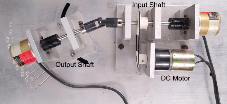
The purpose of this demonstrator is to show students how a universal joint works. Wikipedia describes a universal joint with the following statement.
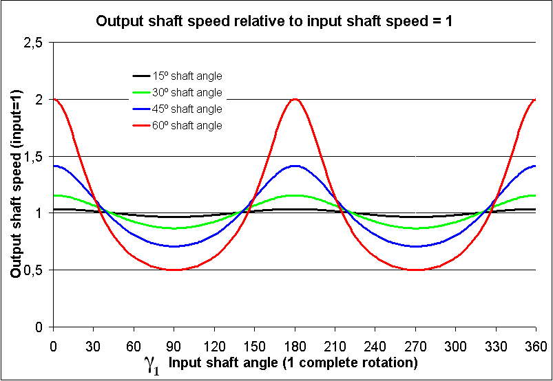
This demonstrator unit will clearly show that the universal joint is not a constant-velocity joint. The speed of the output shaft varies with the position of the input shaft. To see this we define variables for the following quantities:
- \(\beta\): Bend Angle – Angle between the input shaft and output shaft with \(0^{\circ}\) representing no bend at all.
- \(\gamma_1\): Input Shaft Angle
- \(\gamma_2\): Output Shaft Angle
- \(\omega_1\): Input Shaft Speed
- \(\omega_2\): Output Shaft Speed
The shaft speeds are determined by finding the derivatives or rates of change of the corresponding shaft angle.
$$\omega_1 = \frac{d\gamma_1}{dt}$$
$$\omega_2 = \frac{d\gamma_2}{dt}$$
This system will measure the shaft angles as a function of time and create the following graphs:
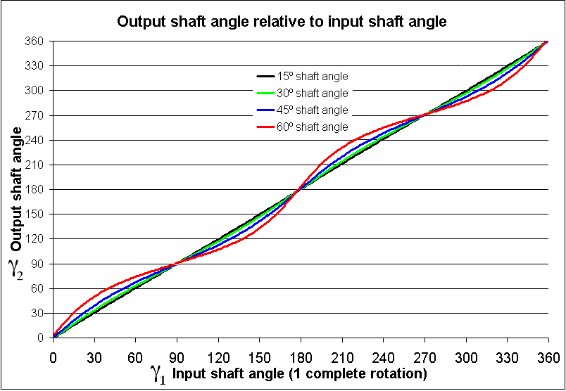
- \(\gamma_2 \textrm{ vs } \gamma_1\): Output shaft angle versus input shaft angle.
- \(\omega_2/\omega_1 \textrm{ vs } \gamma_1\): Speed of the output shaft relative to the input shaft as a function of the input shaft angle.
These measurements will be compared to the theoretical predictions which are described on wikipedia with the following equations and graphs.
| Output Angle vs Input Angle | Relative Speed vs Input Angle |
| $$\gamma_2 = \tan^{-1}\left[\frac{\tan\gamma_1}{\cos\beta}\right]= \tan^{-1}\left[\frac{\sin\gamma_1}{\cos \gamma_1\cdot\cos\beta}\right]$$ | $$\frac{\omega_2}{\omega_1} = \frac{\cos\beta}{1-\sin^2\beta\, \cos^2\gamma_1}$$ |
 |
 |
Project Repository
The source code for the project and all documentation files will be maintained at the following subversion address:
svn://physics.wku.edu/phys318/projects/engineering/mechanical/u-joint/trunk
Each student in the course has read-write access to this location. You should check out this address into a new working copy directory on your local system and routinely make commits to this area as you progress on your work. Be sure to always provide a comment to describe the work in your latest SVN commits.
Project Roles
The project will be divided into the following roles, with each student taking primary responsibility for a particular project area.
- User-Interface Manager [Nick Clayton]
The top-level VI will use a dual-loop architecture with an event loop to handle user-interface events and a queued state machine to handle various program actions. There should be only a minimum number of controls on the front panel described below:- Edit Settings – A boolean button that allows the user to edit the configuration settings.
- Bend Angle, \(\beta\) – A double-precision control that allows the operator to enter the angle between the input and output axes.
- Start / Stop Acquisition – A boolean with a switch mechanical action that will allow the operator to start or stop the data acquisition. When False the button should say Start Acquisition, when True it should say Stop Acquisition.
- Save Data – A boolean with a latch mechanical action that will allow the operator to save the data to a TDMS data file.
When the program starts it should run thru a series of startup procedures including (1) setting the Start / Stop Acquisition button to false, (2) loading the configuration settings from an INI file into a set of global variables clusters (described below), (3) computing and plotting the theoretical data for the current setting of the Bend Angle input, and (4) setting the UI to an Idle State where it waits for an event. The program should respond in the following manner to the events described below:
- Panel Close? – The program should stop when the user hits the red X in the top-right of the front panel window.
- Bend Angle, Value Change – When the user changes the Bend Angle, the application should recompute the theoretical data associated with the Input Angle, Output Angle, and Relative Speed.
- Edit Settings, Value Change – When the user presses the Edit Settings button the global settings clusters for the Input Encoder, Output Encoder, and Trigger should be made available to be edited.
- Start / Stop Acquisition, Value Change – When the user presses the Start / Stop Acquisition boolean the application should test whether the button becomes True or False. If True, then the program should transition to a Run State where the Edit Settings, Bend Angle, and Save Data controls, along with the Panel Close operation, are disabled, and then begin acquiring data. If False, the application should stop the data acquisition and then move to the Idle state where the controls are once again enabled.
- Save Data, Value Change – When this button is pressed the program should present the user with a dialog that will allow the experimental and theoretical data to be saved to a TDMS data file.
- Data Acquisition Manager [Mohammad Alshatti]
A pair of action engines will control the Trigger signal and will measure data from the encoders respectively. These action engines should made by refactoring the examples that perform these functions from the Fall 2020 effort into action engines. Both of these action engines will use the global variables named Input Encoder, Output Encoder, and Trigger shown below. These variables will be loaded automatically at program startup and are available for use inside these action engine subVIs.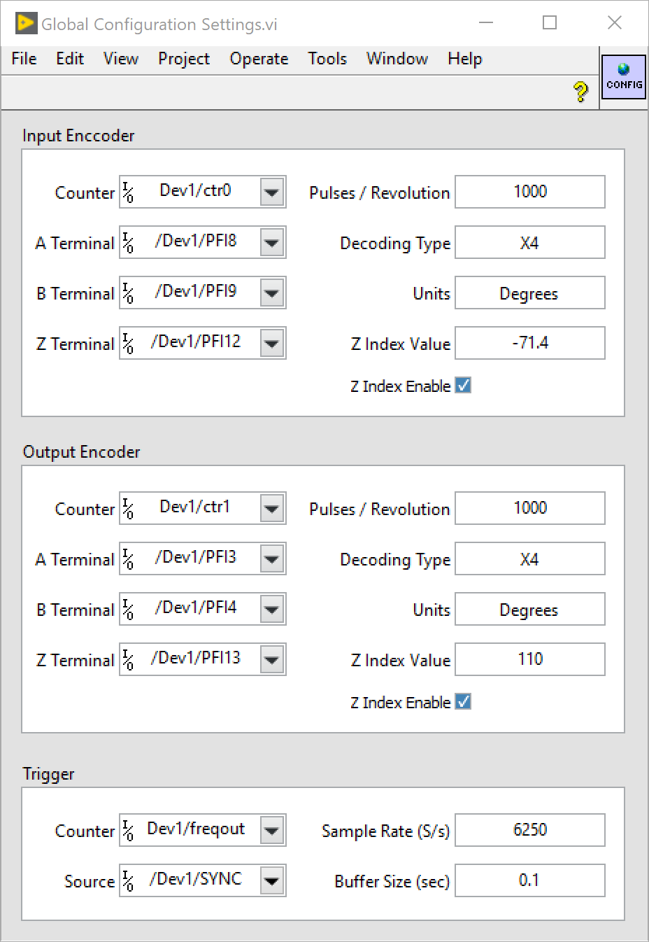
The Trigger Action Engine will create a signal on the SYNC terminal of the NI ELVIS II using a Counter Output task on the freqout channel. This action engine should have Configure, Start, and Shutdown states. The TaskID for this task should be saved in a shift register in this action engine subVI.
The Encoder Action Engine will set up two Counter Input tasks, one for each of the input and output encoders. The TaskIDs for these input tasks should be encapsulated inside this action engine using two shift registers. This action engine should have Configure, Start, Read, and Shutdown States. The Configure state should create the channels for each task, set up the timing for each task, and save the number of data points per buffer in a shift register for the Read State. The Start state simply starts each task. The Read state should measure the output from the two encoders (each of which will be a one-dimensional array) and return this data in a two-dimensional array with the input encoder in the first row and the output encoder in the second row.
- Data Buffer Manager [Jaden Hall]
A data buffer written in the style of an action engine will play a central role in the conversion of the raw input and output angle measurements into speed values as well as making all of the experimental data available to different parts of the application. This VI is the glue that will connect many different aspects of the application together. This VI will maintain data in three shift registers that each contain a double-precision array, one for the Input Angle \(\gamma_1\), one for the Output Angle \(\gamma_2\), and one for the Relative Speed \(\omega_2/\omega_1\). Outside of the action engine while loop, these arrays will be bundled into a type-defined cluster called Data and provided as an output that is returned by the VI.The Data Buffer action engine will support the following actions:- Clear Data – This action will clear each of the data arrays Input Angle, Output Angle, and Relative Speed by filling them with an empty array. In addition, this action should compute an array of time values that will start at 0 and increment by \(dt = 1/f_s\) where \(f_s\) is the Sample Rate available in the Trigger global variable cluster. The array of time values should have the number of points determined by \(N = f_s\cdot\Delta t\) where \(\Delta t\) is the Buffer Size in seconds, also available in the Trigger global variable cluster. This array will be used in the Insert Data action for differentiating angles to find speeds so it should be stored in an additional shift register to be available when needed.
- Insert Data – This action will accept a two-dimensional array of double precision numbers direction from the Data Acquisition action engine as inputs. This array will contain the raw, instantaneous readings from the input angle encoder and the output angle encoder. The input angles will be in row 0 of the array and the output angle will be in row 1 of the array. In this action these small buffers of data will be converted into a single point for each of the values Input Angle, Output Angle, and Relative Speed and appended to the corresponding arrays in the shift register. However, there are many subtle issues that must be observed here. First, after a new data set is started, all data should be ignored until both input and output encoders pass their zero index. Otherwise, the angle data is not correct. Secondly, if a buffer of data happens to pass through the 360 to 0 degree transition then there will be a discontinuity in the data that will effect the average angle and the speed (slope of \(\gamma\) vs \(t\)). A routine was developed in the Fall 2020 semester that takes care of this issue and it should be used for processing both the input angle and output angle mini buffers.
- Get Data – This action simply returns all of the data in the buffer. The data should be in a cluster named Data consisting of the three arrays Input Angle \(\gamma_1\), Output Angle \(\gamma_2\), and Relative Speed \(\omega_2/\omega_1\).
- Theory Manager [Saud Alanzi ]
This subVI will be written in the style of an immediate subVI that computes the theoretical values of the Output Angle and Relative Speed as a function of Input Angle. The subVI should accept a double-precision control named Bend Angle which will be angle between the input shaft and output shaft in degrees. It should create compute the Input Angle, Output Angle and Relative Speed using the formulas described at the top of this document for one-degree increments of the input angle from \(0^{\circ}\) to \(3600^{\circ}\). The data should be returned in a cluster consisting of the three arrays using the same type definition used for the Experimental Data described in the Data Manager section.
The Theory Manager will be responsible adding this subVI as needing in the Top Level application after the basic structure is completed by the User Interface Manager.
- Data Storage Manager [Abdulwahab Alnajdi]
This subVI will be written in the style of an immediate subVI that will save both the theoretical and experimental data to a TDMS formatted data file. The subVI will have two copies of the Data cluster as input controls, one for the Experimental Data and one for the Theoretical Data. The subVI should prompt the user for a file path to save the file and should save the data to that file. It should exit gracefully if the operator cancels the save operation.
The Data Storage Manager will be responsible adding this subVI as needing in the Top Level application after the basic structure is completed by the User Interface Manager.
- Configuration Settings Manager [Professor Harper]
Routines will be provided for loading and saving the global configuration clusters from and to an INI style configuration file. In addition, a routine will be provided for editing the global configuration clusters while they are in memory. The User Interface Manager should provide program states for these actions in the queued state machine. The Configuration Settings Manager will add the code to these states.
- Graph Manager [Professor Harper]
This subVI will be an action engine subVI that will encapsulate the code necessary for maintaining the XY graphs of Output Angle versus Input Angle and Relative Speed versus Input Angle. It will have the following three actions Initialize, Insert Theory, and Insert Data. The Initialize action will accept references to the two graphs that will be stored in shift registers for use by the other actions. The Insert Theory and Insert Data actions will insert the theoretical and experimental data respectively onto the graph.
:
:

