Demonstration
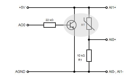
Circuit Details
 |
 |
Requirements
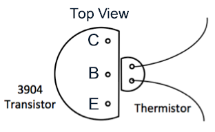
Create an application that will allow an operator to control the temperature of a small heat plant. The heat plant consists of a 2N3904 NPN transistor and an attached thermistor. The thermistor (Vishay NTCLE100E3, 10 kΩ @ 25 °C) is packaged in a round epoxy bead. One side of the bead has been sanded off in order to create a flat spot to improve heat transfer. The joint thermal conductivity is improved by using thermal grease between the components. The transistor and thermistor are held together with heat-shrink tubing. A styrofoam bead can be used as thermal insulation.
You may wish to use some components from assignment A02 in this project. The application should…
- measure the temperature of the system using the thermistor, and
- control the system using PID to adjust the voltage applied to the transistor in order to drive the heat plant temperature to a selected setpoint.
- have options for either open-loop or closed-loop (PID) control of the plant. Use a tab interface to separate the controls needed for the open-loop vs closed-loop cases.
In addition, the main VI should…
- plot the temperature, setpoint, and transistor control voltage on a strip chart style waveform chart,
- stream the temperature, setpoint, and transistor control voltage values to an automatically created tab-delimited text file (with column headers),
- continue to run until an error occurs or the operator hits a STOP button, and
- turn off the heater (set the control voltage to zero) prior to shutting down.
The chart should…
- have a temperature scale on the left-hand side for the temperature and set point,
- have a scale on the right-hand side for the control voltage (it should have a fixed range from 0 to 10V),
- clear any previous data when the program starts (use a Property Node to reset the History Data of the Waveform Chart), and
- show a plot legend along with a digital display for each plot.
Top-Level VI Details:
- Use a continuous loop design pattern for your top-level VI.
- On the front panel provide controls listed below with data types and default values set to the values in square brackets:
- Temperature Units [Type Defined ENUM, Fahrenheit] – Controls the display units for the temperature. Allowed values should be Celsius, Fahrenheit, Kelvin, and Rankine.
- Measurement Period (s) [DBL, 0.2s] – Used with software timing to control the time between successive measurements. Your application should respond to changes in this parameter while it is running.
- Temperature Setpoint [DBL, 95] – The temperature setpoint (in same units as Temperature Units).
- Shutdown [BOOLEAN, FALSE, Latch When Released Mechanical Action] – A button the user can press to stop the data collection when desired.
- Control Mode [Enum, Close-Loop] – A tab control (which shows up on the block diagram as an enumeration) with values of Open Loop or Close Loop.
- PID Gains [Cluster, values that will work] – A cluster containing the PID parameters for the system. Right click on the appropriate input of the PID subVI in order to Create this control. This control should be placed on the Closed Loop page of the Control Mode tab control.
- Manual Control [DBL, 0] – A numeric control that can be used to manually set the voltage applied to the base of the transistor when operating in Open Loop control mode. This control should be on the Open Loop page of the Control Mode tab control.
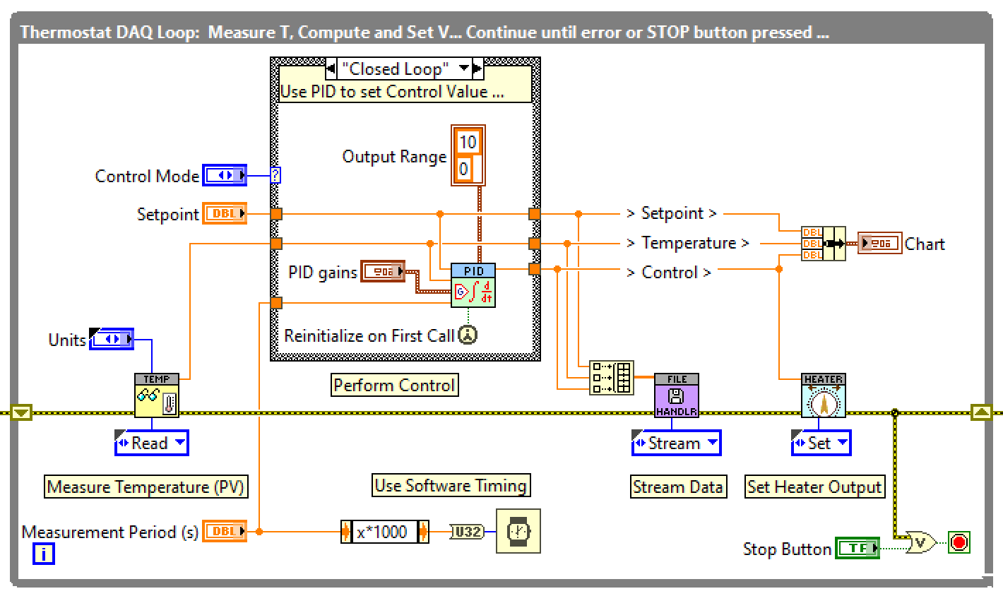
- The image below can be used as reference to help with the continuous loop portion of the top-level VI. Initializing the action engines (before the loop) and shutting them down (after the loop) is not shown.
- Your DAQmx VIs to measure the temperature and control the transistor and the VI to stream the data to disk should be encapsulated into Action Engines as described below.
Action Engine subVIs
1. Read Thermistor Action Engine
- Encapsulate the code for measuring the temperature with the thermistor into a subVI written in an Action Engine design pattern.
- Use the “Find myDAQ.vi” subVI to automatically locate a connected myDAQ and use the analog input channels as shown in the circuit diagram above.
- The DAQmx TaskID should be stored in an uninitialized shift register in this subVI. In this manner the TaskID wire will not be necessary at the top-level of your application.
- This subVI should have the following controls and indicators
- AI Actions: A type-defined enum specifying the following possible “actions”: Initialize, Read, Shutdown
- Initialize should automatically create the channels, start the task, and store the TaskID in a shift register.
- Read should Read the voltages and convert them to temperature in the appropriate units.
- Shutdown Should stop and clear the task and store an empty TaskID in the shift register.
- Temperature Units: An enum to select the temperature units.
- Temperature: A numeric indicator (DBL) used for returning the temperature in the selected units.
- Standard Error In and Error Out clusters
- AI Actions: A type-defined enum specifying the following possible “actions”: Initialize, Read, Shutdown
2. Control Heater Action Engine
- In a similar manner, encapsulate the code for controlling the transistor base voltage into a separate Action Engine with the DAQmx TaskID stored in a shift register. Create a separate enum, called AO Actions for the different actions of this subVI: Initialize, Set, and Shutdown.
3. Stream Data Action Engine
- Create a general purpose action engine for streaming data to a tab-delimited text file.
- The subVI should have the following controls and indicators:
- File Actions: A type-defined enum with the following possible “actions”: Initialize, Stream, Close
- Initialize should automatically create a file named with the current date and time as YYYY-MM-DD-HH-MM-YourLastName.txt in a folder called “Data” on your desktop, accept an array of string headers and write the strings on the first line of the file separated by tab characters. and store the File Refnum in an uninitialized shift register.
- Stream should accept an array of data and write the array to a line in the file with each value separated by tab characters (use “%6g” format string).
- Close should close the file and dispose of the file refnum. An empty refnum will have to be stored in the shift register.
- Headers: An array of strings with names of the column headers used during the Write Header action.
- Data: A DBL array of values used during the Stream action.
- Standard Error In and Error Out clusters.
- File Actions: A type-defined enum with the following possible “actions”: Initialize, Stream, Close


