There are numerous settings in the LabVIEW environment can be customized on a per-user basis. The video below gives a quick summary of some of the changes that are recommended to the configuration of the LabVIEW environment to promote best practices while programming.
The computers in the WKU Department of Physics and Astronomy have been modified as described below with the changes from the default configuration. These settings are recommended to assist with good wiring habits that promote good block diagram style.
Start up LabVIEW and then select Tools>Options…from the menu, and follow the directions below to setup your LabVIEW installation in the recommended configuration.
Front Panel Settings
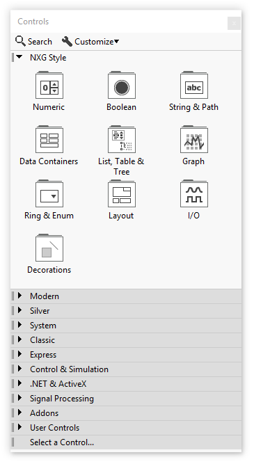
- Set Control Style for New VIs to Fuse Design System (formerly “NXG Style” as shown in the picture below).

Block Diagram Settings
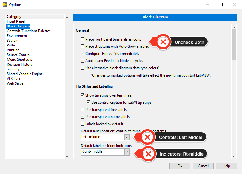
- Uncheck ‘Place front panel terminals as icons’.
- Uncheck ‘Place structures with Auto Grow enabled’.
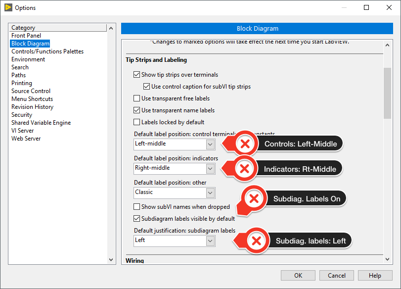
- Set ‘Default label position: control terminals and constants’ to ‘Left-middle’.
- Set ‘Default lab position: indicators’ to ‘Right-middle’.
Scroll down slightly and also set the following which will promote better documentation of sub diagram structures:
- Check ‘Subdiagram labels visible by default’.
- Set ‘Default justification: Subdiagram labels’ to Left
Scroll further down the Block Diagram options pane and:
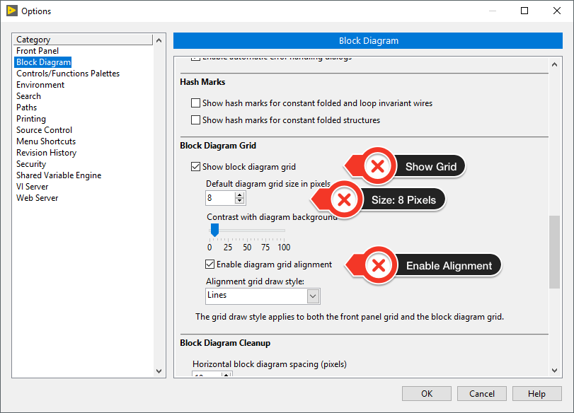
- Check ‘Show block diagram grid’.
- Set ‘Block diagram grid size in pixels’ to 8.
- Check ‘Enable diagram grid alignment’.
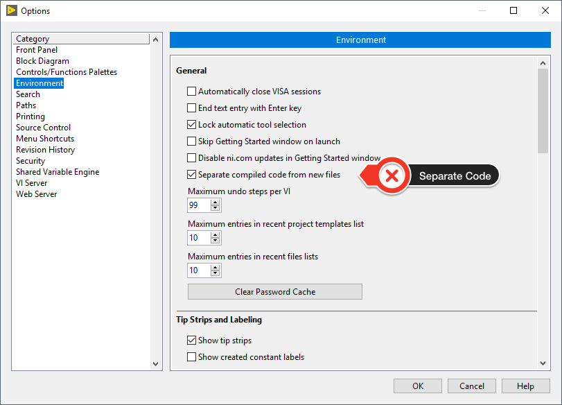
Environment
- Check ‘Separate compiled code from new files’.
Controls/Functions Palettes
- Under Palette: Select ‘Category (Icons and Text)’.
![]()
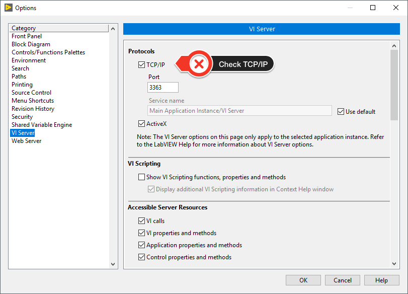
VI Server
- Make sure the TCP/IP box is checked. It might already be checked.
Click OK to save these changes to the LabVIEW Options !!
Palette Visibility
Another issue that sometimes causes confusion is that by default LabVIEW only shows the most commonly used sub-palettes on the Controls (front panel) and Functions (block diagram) palettes. The WKU Physics and Astronomy computers are set to show all of the sub-palettes so that all controls/indicators and functions are visible. To make this change on your computer perform the following:
-
- From the LabVIEW Getting Started window select the menu option File>New VI. You will see two new windows appear, the Front Panel (or user interface) with a grey background, and the Block Diagram (where the LabVIEW code goes) with a white background.
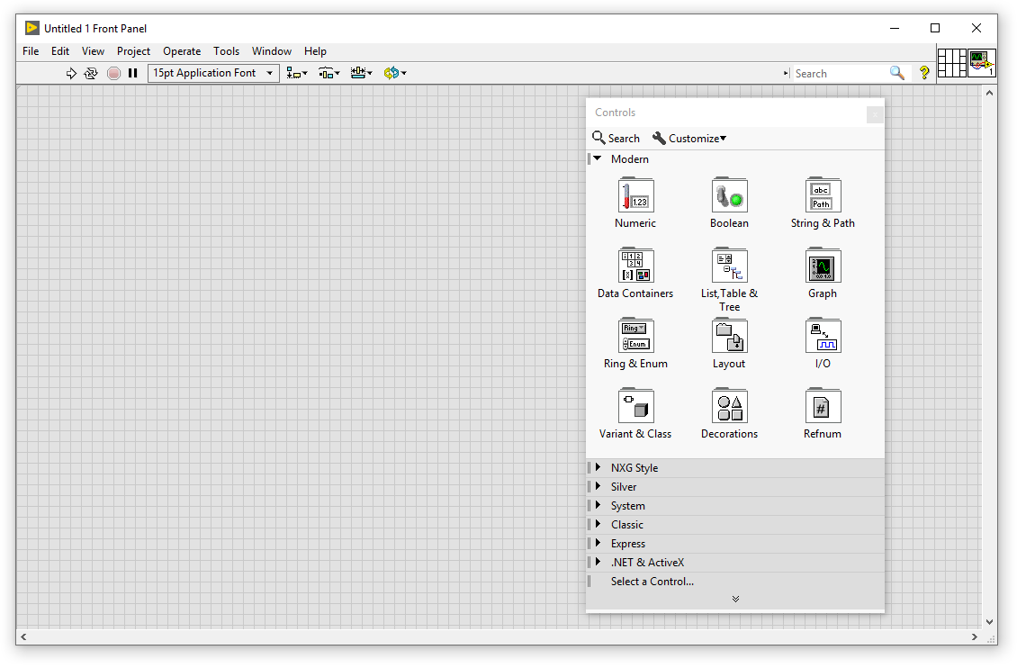
- The Controls palette may also be present as shown in the image below. This window can be moved around anywhere you like and may be present anytime you have a LabVIEW front panel as the top-most window.
-
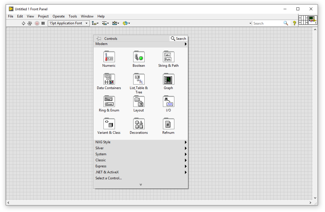
- If the Controls palette isn’t visible you can make it appear by right-clicking on the Front Panel of a VI as shown below. This type of palette appears when you right click and it will disappear when a selection is made. To turn it into a floating palette you can click the thumbtack in the top left corner to “pin” it down.
-
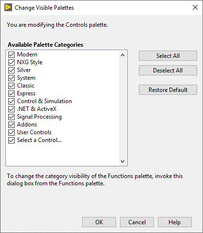
- In either case, select the downward arrow at the bottom of the Controls palette to cause it to fully expand and then select ‘Change Visible Palettes’. From the dialog that appears, choose ‘Select All’ and then press ‘OK’. This will cause all of the available controls to always appear.
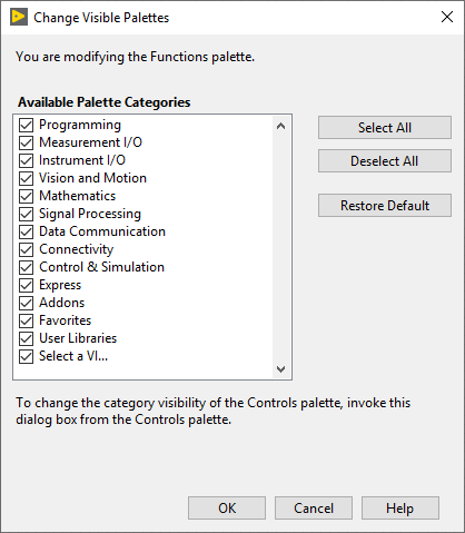
- Repeat this process for the Functions palette on the Block Diagram.
You should also place the Fuse Design System Controls sub-palette on the top of your Front Panel palette. Do this by:
-
- Pop-up (right-click) on the Front Panel of a VI to display the Controls palette.
- Click the thumb-tack to pin the palette to a floating style palette window.
- Using the handle (two small vertical lines) on the left of the Fuse Design System Controls sub-palette (formerly NXG Style as shown below) drag it to the top of the Controls palette and release it. You can close this palette and the position of the Fuse Design System controls will be remembered and will always appear at the top.