The ADXL335 is a complete 3-axis acceleration measurement system. The ADXL335 has a measurement range of ±3 g minimum. The output signals are analog voltages that are proportional to acceleration. The accelerometer can measure the static acceleration of gravity in tilt-sensing applications as well as dynamic acceleration resulting from motion, shock, or vibration. In the near static situations one can use software timing when carrying out the data acquisition. However, for shock and vibration type measurements higher sample rates will be required forcing the use of hardware timing.
Pinouts
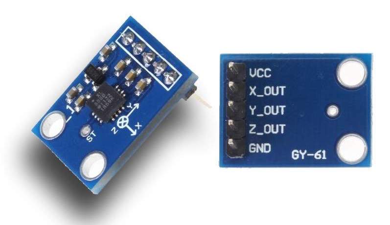
The version that we use is mounted on a small PCB in a package with a part number of GY-61. This package provides a regulated supply voltage of 3.3V to the accelerometer and includes resistors and capacitors to filter the output as described in the datasheet (below). The GY-61 provides connections for 5 pins as described below.
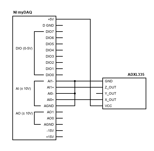
The above diagram shows the ADXL335 connected to the myDAQ with the x-component of acceleration connected to ai0 and the z-component connected to ai1. Don’t forget that both of the negative sides of the analog input channels should be connected to GND.
Scaling Information
Scaling the output of the ADXL335 to engineering units (acceleration in units of g‘s) is a little tricky because the datasheet specifies the scaling parameters assuming the chip is powered with a 3V supply.
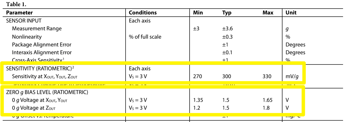
However, as you notice in Table 1 of the datasheet above, the sensitivity (scale factor, \(S\)), and zero-g bias voltage (offset, \(V_0\)) are both ratiometric. This means that the scale factors vary proportionally to the supply voltage. At \(V_S\) = 3.0V the output sensitivity is typically 300 mV/g, but at 3.3 V it will be 330 mV/g = 0.330 V/g. The zero g bias output is also ratiometric, thus the zero g output is nominally equal to \(\frac12 V_S\) at all supply voltages or 1.65V when \(V_S\) = 3.3V.
With these values we can scale the measured voltage \(V\) to an acceleration (in g‘s) by first subtracting the zero g bias voltage to adjust the zero reference and then dividing by the scale factor to convert to proper units.
$$a = \frac{1}{S} (V – V_0)$$
If you need to write this transformation in the form of a slope (\(m\)) and intercept (\(b\)) then you could rewrite the equation as
$$a=mV + b = \frac{1}{S}V – \frac{V_0}{S}$$
making it easy to identify the slope as \(m=\frac{1}{S}\) and intercept as \(b = – \frac{V_0}{S}\).
This linear conversion from voltage to acceleration is depicted in the desmos.com graph below. Notice that the voltages that you should expect at -1g, 0g, and +1g respectively are approximately 1.32V, 1.65V, and 1.98V. If your values vary slightly from these it is possible that the supply voltage isn’t exactly 3.3V.
Datasheet
 Loading...


