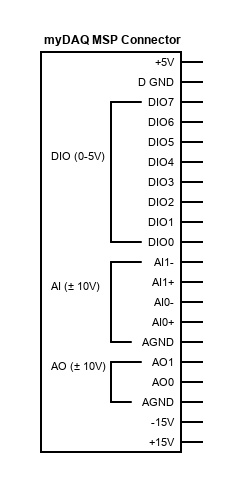
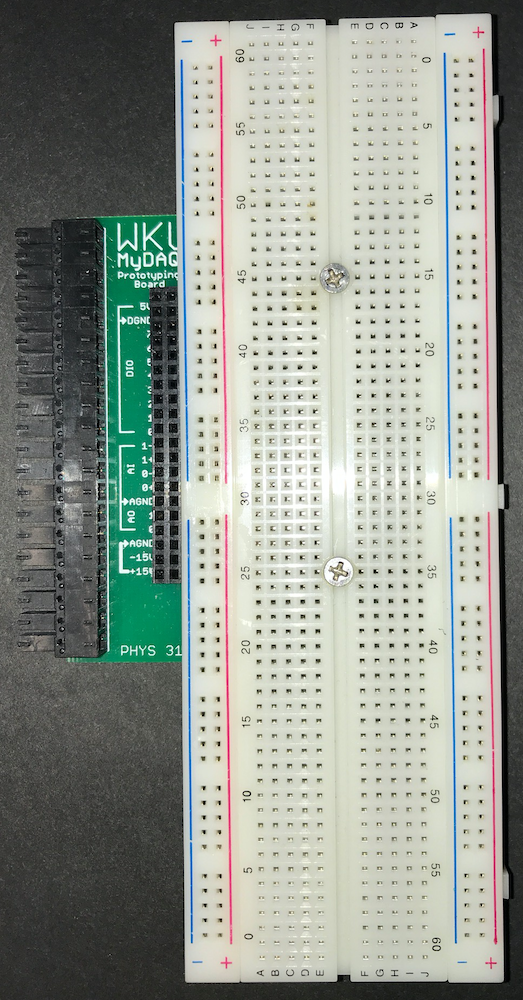
We will connect various electronic components to our myDAQ using a prototyping breadboard like the one shown below. We have attached a standard small breadboard to a signal breakout board that will plug into the myDAQ 20-pin Mini System Port (MSP) connector. A 2×20 pin header can be used to connect these 20 signals (+5V, -15V, +15V power, analog and digital ground, two analog output channels, two analog input channels, and 8 digital I/O channels) from the myDAQ to the circuit you build on the breadboard.
 |
 |
These breadboards have two bus strips along each side that are usually used for power and ground busses, and several terminal strips consisting of parallel rows of five pins each that run perpendicular to the bus strips.
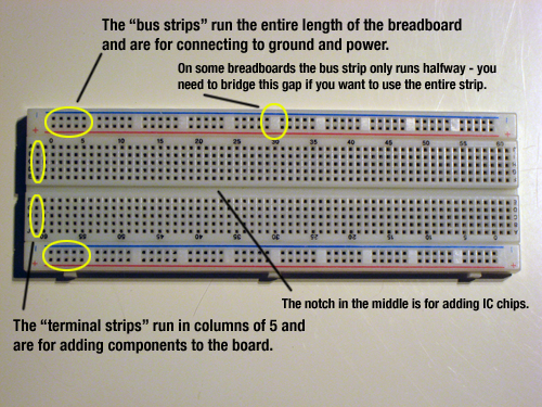
Here is another view showing which pins are connected to each other on our breadboards.


