Big Dish Telescope: Original System
The original television receive-only (TVRO) system acquired from the Hurt family consisted of these components:
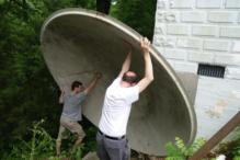
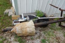
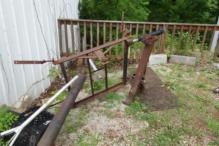
- 10-foot diameter parabolic fiberglass dish of unknown manufacture (see photos above), with
- embedded metal foil reflective surface
- focal ratio of 0.31 (inferred from 2-foot dish depth*)
- steel support post and modified polar mount hardware
- linear actuator for slewing east-west along satellite belt
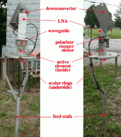
- 5-foot Chaparral feed stalk (see photos at right), with
- scalar rings to keep radiation outside dish area from entering feed
- rotatable resonant element to capture polarized signals at the dish focus
- radio-frequency (RF) waveguide carrying the signal from the resonant element
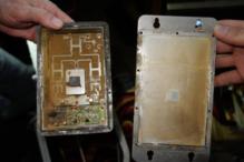
- low-noise RF amplifier (LNA)
- Uniden single-channel frequency downconverter from 3.7-4.2 GHz received RF to 70 MHz intermediate frequency (IF)
- direct-current (DC) power (probably 24-volt) and coaxial feed lines (probably RG-6 75-ohm TV coax) through the feed stalk, cut off at the stalk base
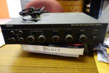
No "set-top" box was included, although one was made available by Henry
Cantrell, a retired electrical engineer and active radio amateur. TVRO set-top
boxes were used not only to demodulate and amplify the IF signal for TV display
but also to control the east-west slew motor, polarizer stepper motor, and
downconverter local oscillator (called a voltage-controlled oscillator). The
original satellite broadcast stations had a bandwidth of about 36 MHz or a
bit less, and after mixing down to the IF, one was selected with a bandpass
filter in the receiver tuner.
Benchtop experiments in Mr. Cantrell's lab were successful in putting both
broadband continuum noise and narrowband oscillator signals through the LNA.
Unfortunately, the downconverter had a short circuit and underwent thermal
failure when tested.
*The focal ratio of a parabolic dish reflector can be
calculated as
f / D = D / (16 × d), where f is the focal length, D is the dish
diameter, and d is the dish depth
(see Chaparrall
Communications Feedhorn Troubleshooting Guide).
Conversion to Radio Telescope
Several aspects of the TVRO system required modification to convert it into
a functioning radio telescope.
- Dish Integrity: When recovered, the dish had a crack on one side that did not affect its
utility as a reflector but reduced its structural integrity and might allow
moisture or other contaminants to penetrate its outer surface. This problem
was addressed by patching the fiberglass exterior of the dish, strengthening
and sealing it from the elements.
- Pointing Ability: The TVRO system used a
so-called polar mount
designed to track geosynchronous satellites, which all appear along an arc
about 5 degrees south of the celestial equator from the latitude of southern
Kentucky, and it only needed to slew east and west along this arc. To observe
targets elsewhere in the sky, the system must be able to point away from this
arc, ideally to any north-south position
(called "Declination"
in astronomy).
To address these issues, WKU engineering students and faculty have investigated
a variety of much more versatile mechanical designs in a series of courses
(ME 400 & 412, ENGR 490 & 491). Assembly of the redesigned system
is in progress.
- Slewing and Tracking: The TVRO system had no ability to track
objects at a speed matching that of astronomical sources,
which appear to drift
from east to west at 15 degrees per hour on the celestial equator. Such
tracking is desirable for observing faint sources to add up the received signal
over time. The engineering team is also working on this issue.
- Sensitivity and Bandwidth: The original LNA was an early and probably quite
noisy model by today's standards, and it required a separate frequency
downconverter that is no longer functional. Newer and better subsititutes for
both are now available, so we plan to replace the entire feed assembly. We
have purchased a
Chaparral C-band low-noise
block downconverter and feed (LNBF), a single unit that combines the feed,
LNA and dowconverter functions. The LNBF has far lower noise temperature
(17 kelvins, where the old LNA may have been over 100 K), larger RF
bandwidth (3.4-4.2 GHz), and much broader IF coverage (800 MHz
"untuned" over 0.95-1.75 GHz); these combined attributes will allow much
more sensitive and versatile astronomical observations. We are also planning
to install receivers for other frequency bands, such
as Chaparral's Ku-band
LNBF, or even a 1.4 GHz L-band feed
to detect 21-centimeter hydrogen emission.
- Signal Capture: The TVRO electronics had no means of recording the received signal, as is
desirable for experiments. While a VCR or DVR could capture demodulated
television signals, these have limited bandwidth, and natural signals will be
corrupted by the demodulation process. We have instead purchased
software-defined radio (SDR) receivers for signal capture, including a simple
RTL-SDR and more
sophisticated Airspy R2
and SDRPlay RSPdx SDRs and plan to
record signals off one of these using either
a Raspberry Pi board computer
or a laptop PC. WKU physics students in the Data Acquisition Using
LabVIEW course (PHYS 318) are working on this project.
- Control Systems: Lastly, the TVRO had no overall control system
other than the original set-top box (see above), which is not suitable for
astronomical observations. We are working to implement joint controls of both
the telescope pointing and data acquisition processes using
the LabVIEW interface
platform from National Instruments. PHYS 318 and ME 400/412
students are working on different parts of the control system. Our eventual
goal is to make the radio telescope remotely operable from the WKU campus for
the benefit of students, faculty, and the public.
This project is ongoing.
A few highlight images of work on the
telescope and some of the people involved are available.
Please see the credits page for a complete list
of all who have contributed.
Radio Projects
|
Big Dish
