 In this section we hope to describe how the voltage across a capacitor will behave in a circuit as a function of time.
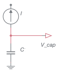
In the simple case of a current source in series with a capacitor as shown to the right, the current would be constant and we would expect the voltage to increase at a constant rate since \(I=C\cdot\textrm{d}V/\textrm{d}t\). A small current would create a voltage versus time that increased linearly with a small slope, and a larger current would result in a larger slope of \(V\) vs \(t\). Such a waveform would be called a ramp. The only problem is that current sources, especially ideal sources where the current is constant, are not that common.
Instead, we will consider the slightly harder case of a constant voltage source in series with a resistor and capacitor.
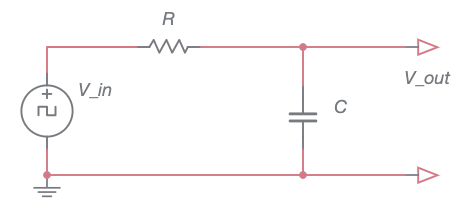
Here the voltage across the capacitor, labeled \(V_\textrm{out}\) in the above schematic, will approach the applied voltage (\(V_\textrm{in}\)), but at a rate that diminishes toward zero as the capacitor voltage reaches its maximum.
To analyze this circuit let’s assume that our device for measuring \(V_\textrm{out}\) doesn’t draw any current. Then the current through the resistor and the current thru the capacitor will be the same. Using Ohm’s law for the resistor we have
$$I_R = \frac{V_\textrm{in}-V_\textrm{out}}{R}.$$
for the current thru the resistor. But the current thru the capacitor will be
$$I_C = C\frac{\textrm{d}V_\textrm{out}}{\textrm{d}t}.$$
Since these two expressions for current are equal we can equate these terms and rearrange slightly to obtain the following differential equation for \(V_\textrm{out}\)
$$V_\textrm{in}-V_\textrm{out} = RC \frac{\textrm{d}V_\textrm{out}}{\textrm{d}t}$$
Rearranging this as
$$V_\textrm{out} + RC \frac{\textrm{d}V_\textrm{out}}{\textrm{d}t} =V_\textrm{in}$$
reveals it to be a inhomogeneous, first-order, linear differential equation with constant coefficients. This equation has a general solution
$$V_\textrm{out}=V_\textrm{in}+Ae^{-t/RC}$$
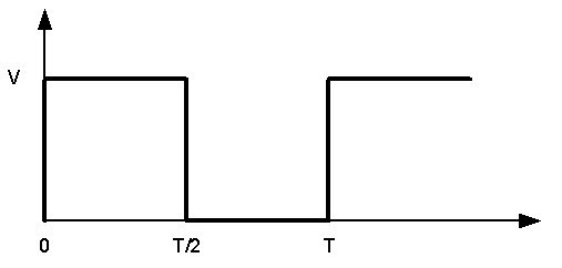
where we need to find \(A\) based upon the initial conditions. To do this let’s consider the input voltage to be a square wave that switches off and on from 0 to some maximum \(V\) with a period \(T\).
Charging
First we consider the case when the output voltage is initially off \((V_\textrm{out}=0)\) and the input is switched on at \(t=0\) to \(V_\textrm{in}=V\). If we apply these initial conditions we obtain
$$V_\textrm{out}=V_\textrm{in}+Ae^{-t/RC}$$
$$0 = V +Ae^0$$
leading to \(A=-V\). Substituting this into the general solution gives a final result of
$$V_\textrm{out}=V(1-e^{-t/RC}).$$
The product \(RC\) has units of \(\Omega\)F which reduces to seconds. This product is commonly called the time constant for the circuit and is denoted with the symbol \(\tau = RC\). The graph below shows the voltage across the capacitor in units of \(\tau\). It shows that the voltage across the capacitor will have reached 63.2% of its maximum value after 1 time constant has elapsed and that the capacitor is essentially fully charged after about 5 time constants.
Discharging

