- Oscillators – circuits that repeat an operation over and over, endlessly, in order to set the frequency of an output waveform.
- Differentiators – circuits that respond to changes.
- Integrators – circuits that that respond to averages.
- Filters – circuits that favor one frequency over another.
The schematic symbol for a capacitor actually closely mimics its construction as a set of parallel plates separated by a gap through which charges cannot physically flow. A capacitor is created out of two conducting plates and an insulating material called a dielectric. The metal plates are placed very close to each other, in parallel, but the dielectric sits between them to make sure they don’t touch.
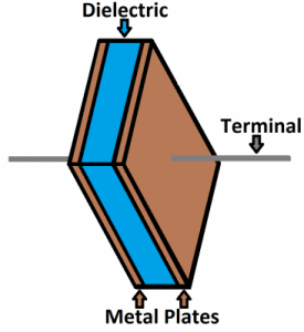
Thinking about these plates at the circuit level, when a current starts to deposit charge on one of the plates the charge carriers on the other plate will feel a force causing the opposite polarity to be induced on its surface. The two plates will have equal and opposite charges on their facing surfaces and an electric field will be created in the dielectric region between the plates. At this point we say that the capacitor is charged. The voltage across the capacitor plates will be proportional to the amount of charge on the plates. We define the capacitance \(C\), in SI units of farads (F), as the ratio of the positive or negative charge \(Q\) on each conductor to the voltage between them
$$C=\frac{Q}{V}.$$
A capacitance of one farad, or one coulomb per volt, means that one coulomb of charge on each conductor causes a potential difference of one volt across the capacitor.
The capacitance of a capacitor depends on the type of dielectric material \(\epsilon\) used, the area \(A\) of the plates, and the distance \(d\) between the plates according to
$$C=\epsilon \frac{A}{4\pi d}.$$
Many capacitors are made to achieve large area by putting the dielectric between two thin layers of metal foil, the rolling the whole thing up like a roll of paper towels.
While we generally describe the current through any circuit component as the rate of flow of a charge passing through it, you should not forget that actual charges cannot pass through the dielectric layer of a capacitor. Instead, one electron accumulates on the negative plate for each one that leaves the positive plate, resulting in an electron depletion and positive charge on one electrode that is equal and opposite to the accumulated negative charge on the other. Even though charge is not flowing through the capacitor, the charge on the plates will change over time and is given by the integral of the current. So finally, we see that the current “thru” the capacitor is proportional to the rate of change of the voltage across the capacitor
$$I = \frac{\textrm{d}q}{\textrm{d}t} = C\frac{\textrm{d}V}{\textrm{d}t}.$$
Useful Analogy
It may be easier to get a better feel for a capacitor by looking at a hydraulic equivalent as shown in (a) below. We can compare a capacitor to a bucket filled with water. The volume of water stored in the bucket corresponds to the charges on the capacitor; the water level corresponds to the voltage and the size (area) of the bucket is equivalent to the capacitance \(C\). Now when you pour water into the bucket (current flow), the water level (voltage over the capacitor) will increase as shown in (b).
- If you fill the bucket through a thin straw (small \(I\)), the water level \(V\) will rise slowly.
- If you fill or drain through a large fire hose (large \(I\)) the bucket will fill (“charge”) or drain (“discharge”) quickly.

