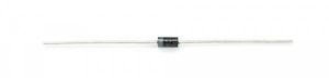
A diode, such as the one pictured above, is an active component that is used to direct the current that is flowing through the circuit by allowing conduction in a single direction only.
Ideal Diode
As we start our discussions of diodes it is useful to model an ideal diode as a device designed to control the direction of current-flow. Current passing through a diode can only go in one direction, called the forward direction. Current trying to flow the reverse direction is blocked. Thus, a diode is like the one-way valve of electronics.
If the voltage across a diode is negative, no current can flow, and the ideal diode looks like an open circuit. In such a situation, the diode is said to be off or reverse biased.
As long as the voltage across the ideal diode isn’t negative, it will “turn on” and conduct current. Ideally a diode would act like a short circuit (0V across it) if it was conducting current. When a diode is conducting current it is said to be forward biased (electronics jargon for “on”).
The “ideal diode” is a convenient fiction which is used when the actual voltage across the diode doesn’t matter enough to be included in a calculation. An I-V curve for an ideal diode is shown below on the left. The model on the right is slightly more realistic and shows a positive bias voltage (also often called the forward voltage) across the diode that must be exceeded in order for it to begin conducting current.
 |
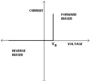 |
| Ideal Diode Model | Slightly More Realistic Model |
The behavior of an ideal diode is summarized in the following table.
| Ideal Diode Characteristics | ||
| Operation Mode | On (Forward biased) | Off (Reverse biased) |
| Current Through | \(I>0\) | \(I=0\) |
| Voltage Across | \(V=0\) | \(V<0\) |
| Diode looks like | Short Circuit | Open Circuit |
Circuit Symbol
Every diode has two terminals and those terminals are polarized, meaning the two terminals are distinctly different. It’s important not to mix the connections on a diode up. The positive end of a diode is called the anode, and the negative end is called the cathode. Current can flow from the anode end to the cathode, but not the other direction. If you forget which way current flows through a diode, try to remember the mnemonic ACID: “anode current in diode” (also anode cathode is diode).
The circuit symbol of a standard diode is a triangle butting up against a line. There are a variety of diode types, some of which are shown below.
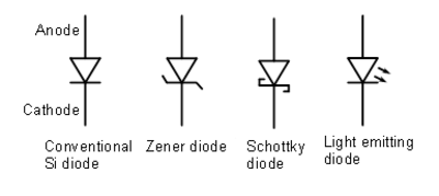
When you see a diode symbol in a circuit you should attempt to evaluate whether the diode is forward or reverse biased. If the potential at the anode is higher than at the cathode by what we will define as the forward voltage then the diode is forward biased and it will act like a closed circuit. Otherwise, the diode is reverse biased and will act as an open circuit.
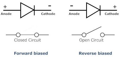
The terminal entering the flat edge of the triangle represents the anode. Current flows in the direction that the triangle/arrow is pointing, but it can’t go the other way.
Real Diode Characteristics
Ideally, diodes will block any and all current flowing the reverse direction, or just act like a short-circuit if current flow is forward. Unfortunately, actual diode behavior isn’t quite ideal. Diodes do consume some amount of power when conducting forward current, and they won’t block out all reverse current. Real-world diodes are a bit more complicated, and they all have unique characteristics which define how they actually operate.
Current-Voltage Relationship
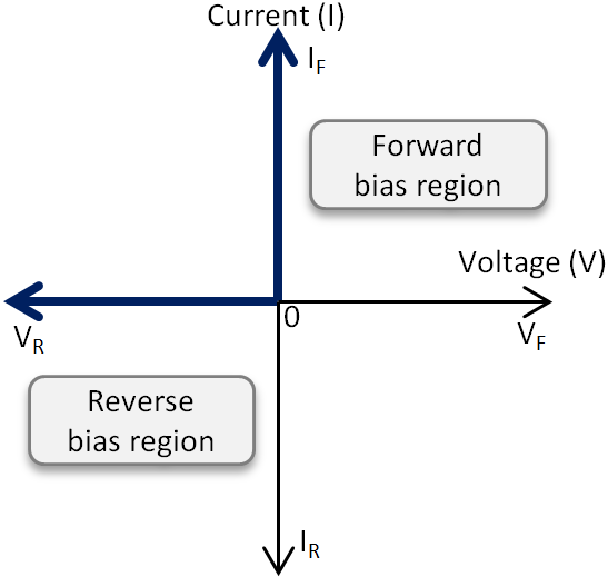
The most important diode characteristic is its current-voltage (i-v) relationship. This defines what the current running through a component is, given what voltage is measured across it. Resistors, for example, have a simple, linear i-v relationship…Ohm’s Law. The i-v curve of a diode, though, is entirely non-linear. It looks something like the following.
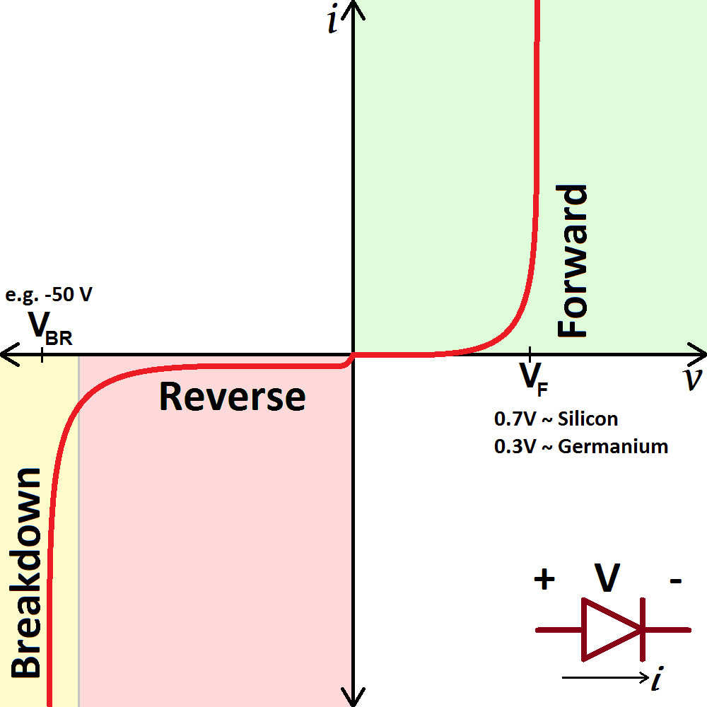
Depending on the voltage applied across it, a diode will operate in one of three regions:
- Forward bias: When the voltage across the diode is positive the diode is “on” and current can run through. The voltage should be greater than the forward voltage (\(V_F\)) in order for the current to be anything significant.
- Reverse bias: This is the “off” mode of the diode, where the voltage is less than \(V_F\) but greater than \(-V_{BR}\). In this mode current flow is (mostly) blocked, and the diode is off. A very small amount of current (on the order of nA) — called reverse saturation current — is able to flow in reverse through the diode.
- Breakdown: When the voltage applied across the diode is very large and negative, lots of current will be able to flow in the reverse direction, from cathode to anode.
Forward Voltage
In order to “turn on” and conduct current in the forward direction, a diode requires a certain amount of positive voltage to be applied across it. The typical voltage required to turn the diode on is called the forward voltage (\(V_F\)). It might also be called either the cut-in voltage or on-voltage.
As we know from the i-v curve, the current through and voltage across a diode are interdependent. More current means more voltage, less voltage means less current. Once the voltage gets to about the forward voltage rating, though, large increases in current should still only mean a very small increase in voltage. If a diode is fully conducting, it can usually be assumed that the voltage across it is the forward voltage rating.
A specific diode’s \(V_F\) depends on what semiconductor material it’s made out of. Typically, a silicon diode will have a \(V_F\) around 0.6 to 1.0V. A germanium-based diode might be lower, around 0.3V. The type of diode also has some importance in defining the forward voltage drop; light-emitting diodes can have a much larger \(V_F\), while Schottky diodes are designed specifically to have a much lower-than-usual forward voltage.
Breakdown Voltage
If a large enough negative voltage is applied to the diode, it will give in and allow current to flow in the reverse direction. This large negative voltage is called the breakdown voltage. Some diodes, such as Zeener diodes, are actually designed to operate in the breakdown region, but for most normal diodes it’s not very healthy for them to be subjected to large negative voltages.
For normal diodes this breakdown voltage is around -50V to -100V, or even more negative.

